
Design Progress | Week 7
- Oct 8, 2025
- 2 min read
Dates: 10/01/25 - 10/07/25
This week's progress was contingent on whether certain parts could be acquired in time. Currently, we are awaiting our ADC multiplexer for the IR sensors, and the momentary/latch switches the team plans to use in the production iteration of NAVI. Thus, I directed my focus to integrating the battery level detector system I designed last week with motor feedback response (similar to how it will function in production), user interface integration (using a simple push button in lieu of our production buttons), our production battery, and our TP4056 USB-C Charging Module.
Pictured below is our intended NAVI production battery:

Then, the assembled aforementioned system, which contains the production battery fed into the TP4056 charging module (which is responsible for feeding power to the rest of the system), a simplified voltage divider to measure voltage level into the Pico 2 ADC2, and our sample test button connected to GPIO15.

Note that the light on the TP4056 charging module is illuminated red. This indicates that it is successfully charging a battery that is not at capacity. Compare this to the image below which shows the LED illuminated blue, indicating that whatever the module is connected to (when disconnected, nothing) is no longer drawing current and is therefore fully charged.

Below is an example measurement of the active capacity of the battery (reading 3.95, better visualized in video)

Example terminal output:

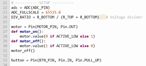
Now the code, same setup as we've done before including pin assignments, ADC setup with voltage divider, and motor active time.


Then a list of tuples is created to assign battery percentages to voltage readings, then linearlly interpolated to give an exact percentage value related to measured voltage.

This system works by "pulsing" the motor one time for each digit in the tens place of the percentage, and each digit in the ones place (i.e. 61% will pulse the motor 6 times, pause, then 1 time). Below we read ADC voltage, define what a "pulse" means for the motor, and assign the pulse percentage logic.

The following is logic for terminal output purposed toward debugging, and actually sending the buzz

Finally, our operational loop awaits a button press to start the system reading:

Video result:


Comments