
Design Progress | Week 4
- Sep 17, 2025
- 3 min read
Dates: 09/10/25 - 09/16/25
This week’s milestone focused on upgrading the NAVI Proximity Headband prototype from simple ON/OFF motor control to proportional PWM intensity control. With PWM, each motor now scales vibration strength based on how close an object is, rather than buzzing at full strength as soon as a threshold is crossed.
I was successfully able to implement PWM motor control on the prototype, mapping sensor voltages to PWM duty cycle (0% at ~1.55V, 100% at ~1.90V). I retained the "panic mode" I implemented for when an object is closer than 100m (the minimum sensor distance), meaning that regardless of a motor intensity/distance curve, panic mode will set the motor to it's highest possible intensity for 200ms. No physical wiring changes needed to be made, but I am worried that continued use without a larger bulk capacitor along the 5V rail could lead to component wear or damage with the varying current surges inherent in PWM control, but I will continue to monitor this.
I also added some powerful features to help manage the unpredictablility of the sensors, which will be discussed below.
The PWM control of the motor makes a night and day difference in conveying a natural feeling feedback to the user, increasing motor strength the closer to an obstacle a sensor gets.
Moving forward I'd really like to start looking into PCB solutions for the system, I can already see how convoluded the device can get with loose components and will not suffice for the production model.
Now is a good time to explain how some of this code is working:
Below, from lines 6 to 36 are many of the "settings" for the prototype. We define things such as the GPIO pins being used, setting the active low signal to False (can change depending on type of motor/multiplexer being used), voltage boundaries for each sensor, panic mode toggle and parameters, ADC values, as well as some useful features such as the Infinite Impulse Response Filter (IIR) smoothing factor. (IIR essentially blends a current reading with a previous reading to "smooth" the data on software level). Setting this value to 0.35 (closer to 0) means the system will favor the previous value rather than a new value, boosting stability at the expense of reactiveness. (This can be tailored after more testing)

Lines 38 to 63 define some hardware specifications. We start by creating 3 ADC objects for GPIO 26, 27, and 28. We use a tuple to form these objects, as it allows for dynamic allocation of GPIO pins while maintaining an index structure for ADC objects. Then, for each motor signal pin, we create a PWM object which stores a frequency value. Next, a function to define a motor's PWM duty is constructed, which takes and integer index and duty value (on or off) float as arguments. We also handle artifact values by clamping between 0.0 and 1.0. Because PWM in micropython uses a 16-bit duty cycle, we multiply the float value by 2^16 (65536), and convert it to an integer (we handle active low by adding a conditional flip statement). After that, we write the computed duty cycle to the PWM hardware on the pico, more documentation on this can be found here : https://docs.micropython.org/en/latest/library/machine.PWM.html. Finally a function is defined to read and average the ADC value, returning both node voltage and raw bit voltage. To do this, we accumulate 8 raw readings and find the average integer.

Here we setup state tracking and sets motors to off at boot. We define the number of sensor motor pairs (n) and initialize a list of IIR smoothed voltage values for each pairing. We also initialize a list to determine panic mode length upon a panic trigger.

Now we can setup our runtime loop, we have some terminal logging throughout the program but I'll focus on the operational logic for now. We begin a for loop which iterates for each of the sensor motor pairs, and first checks each channels voltage and raw ADC. We then apply our IIR smoothing, handling the initial case where we arrive at the first measurement. Next, we check for a panic state by comparing whether panic mode is active and smoothed voltage value, and if present, set a future deadline (ticks_add) to end the panic mode. The final line in the below section helps filter out of bounds measurements by setting a boolean check for if smoothed voltage is inside usable range.

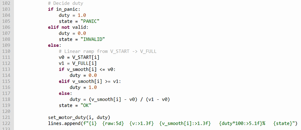
Then we can throw the actual panic state depending on the result from the previous section, as well has determine whether or not the reading is valid at all (i.e. out of range). If all is well, then we linearlly map vsmooth from start to full. Finally we apply the motor duty (line 121) to its respective PWM channel.
Below is an example of some terminal outputs, with labels included:


Comments